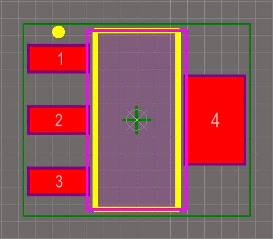
The footprint defines the space the component occupies and provides the points of connection from the component pins/pads to the routing on the board. In the example footprint below, most of the component outline is defined on a mechanical layer (the green lines) rather than the (yellow) overlay, because this component will be mounted so that it hangs over a cutout in the board. A typical footprint includes pads and a component overlay, and can also include any other mechanical details required. The area that the component occupies on the fabricated board is defined by the component footprint. Position and Routing the Jumpers on the PCB.Suggested Workflow for Working with Jumpers.


 0 kommentar(er)
